Analog Hall-effect
Analog Hall-effect Description
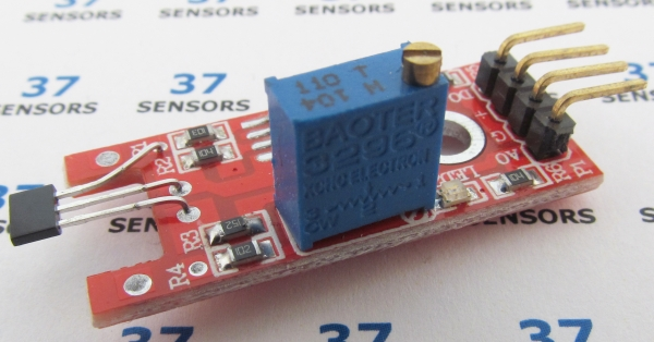
Returns an analog signal based on the intensity of a magnetic field. Module outputs the analog sensor signal, as well as (for some modules) a digital signal that is switched high when the sensor level crosses a preset threshold. The threshold is set via the potentiometer.
Also called: linear hall, magnetic hall, KY035, KY024.
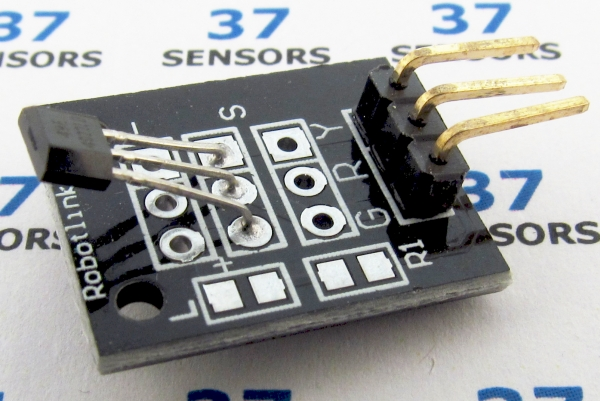
Found in kits: 20 sensors, 37 sensors, 45 sensors (analog only, small board).
Found in kits: 37 sensors, 45 sensors (analog and threshold/digital, longer board).
Analog Hall-effect Specification/Notes:
• Voltage: 3.3V to 5.0V
• LED: Power (longer board)
• LED: Threshold (longer board)
• Size: 15mm X 20mm, 15mm X 35mm
• Main component: SS49E/CYL49E linear hall CYL49E
Sensor board has a potentiometer for sensitivity adjustment. Can be used for current sensing with appropriate circuitry. Use with a magnet for positioning.
There are a number of different sources for these modules. Not every module that looks similar to the ones here behaves exactly the same. Check the specific module that you have for differences in function, voltage levels, pinout, and inactive/active states. Some modules have been found to have incorrectly labeled pins and even poorly soldered components.
Analog Hall-effect Module Pin-out:
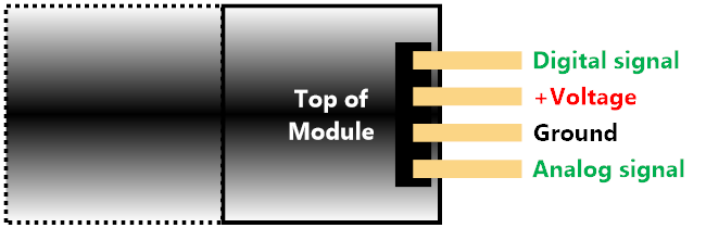
Image: Typical/common pinout for 4 pin module. Always check the pinout for the module that you have.
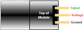
Image: Typical/common pinout for 3 pin module. Always check the pinout for the module that you have.
Analog Hall-effect Test setup with CGMICROKIT1
Read of analog Hall-effect sensor with CGMICROKIT1, console display. This test uses one analog input to read the sensor value every 200 milliseconds. The value is printed out on the console. Mo the maquette assists in holding the magnet near the sensor.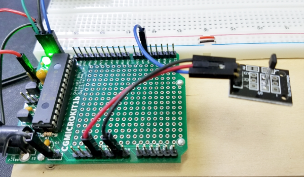
Image: CGMICROKIT1 to analog Hall sensor connections.
• Black wire – Common ground
CGMICROKIT GND - Module Ground
• Red wire – Supply voltage
CGMICROKIT 3.3V - Module +Voltage
• Blue wire – Hall sensor output
CGMICROKIT uM4 (analog input) ⇔ Module analog output
SETPIN 4, AIN
DO
PAUSE 200
X = PIN(4)
PRINT X
LOOP
DO
PAUSE 200
X = PIN(4)
PRINT X
LOOP
Line 1: Set pin 4 to analog input.
Line 3 and 7: Loop forever.
Line 4: Pause for 200 milliseconds.
Line 5: Read the analog sensor input.
Line 6: Print the value.
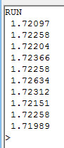
Image: Steady output without magnet present.
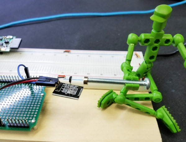
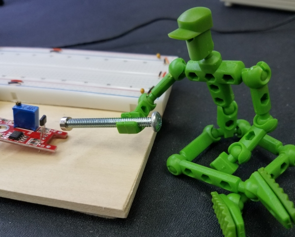
Image: My helper Mo moving the magnet around.
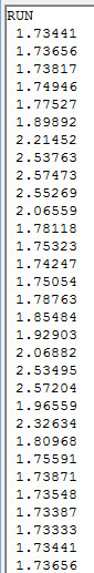
Image: Output with my helper Mo moving the magnet around.
The output with the magnet will vary between a lower voltage (0.66V) and 1.72V (about half of Vcc of 3.3V) with one magnet orientation. Reversing position of North and South magnetic poles make the output vary from the middle/quiescent 1.72 volts to a higher voltage (2.6V).
Analog Hall-effect test
Read of analog Hall-effect sensor with CGMICROKIT1, console display. This test uses one analog input and one digital input to read the sensor value every 200 milliseconds. The value is printed out on the console when the threshold is passed, otherwise, no value is printed. Mo the maquette assists in holding the magnet near the sensor.
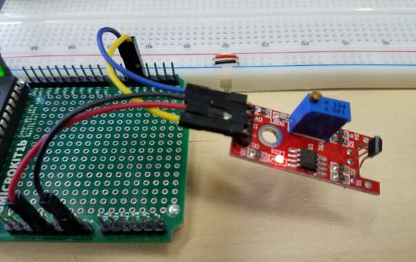
Image: CGMICROKIT1 to linear Hall sensor connections.
• Black wire – Common ground
CGMICROKIT GND - Module Ground
• Red wire – Supply voltage
CGMICROKIT 3.3V - Module +Voltage
• Blue wire – Hall sensor output
CGMICROKIT uM4 (analog input) - Module analog output
• Yellow wire – Threshold/comparator output
CGMICROKIT uM7 (digital input) - Module threshold output
SETPIN 4, AIN
SETPIN 7, DIN
DO
PAUSE 200
D = PIN(7)
IF D = 1 THEN
X = PIN(4)
PRINT X
ENDIF
LOOP
SETPIN 7, DIN
DO
PAUSE 200
D = PIN(7)
IF D = 1 THEN
X = PIN(4)
PRINT X
ENDIF
LOOP
Line 1: Set pin 4 to analog input.
Line 2: Set pin 7 to digital input.
Line 4 and 11: Loop forever.
Line 5: Pause for 200 milliseconds.
Line 6: Read the digital threshold input.
Line 7 and 10: Test for threshold crossing.
Line 8: Read the analog sensor input.
Line 9: Print the value.
Image: No output with magnet farther away than the threshold
Image; Mo moving the magnet around closer than the digital threshold.
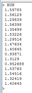
Image: Output with my helper Mo moving the magnet around close to the sensor.
Sensor.Engine: MICRO Analog Hall-effect test
Read of Analog Hall-effect with Sensor.Engine:MICRO, console display. Earlier tests were performed with a CGMICROKIT1. The same tests can be performed with a Sensor.Engine: MICRO.
Read of analog Hall-effect sensor with Sensor.Engine:MICRO, draw on display. This test uses two analog inputs to read the X and Y values displays the joystick position on the S.E:Micro display. Joystick switch press clears the display. This test uses one analog input and one digital input to read the sensor value every 200 milliseconds. The value is printed out on the console when the threshold is passed, otherwise, no value is printed. Mo the maquette assists in holding the magnet near the sensor.
• Black wire – Common ground
Sensor.Engine:MICRO GND - Module Ground
• Red wire – Supply voltage
Sensor.Engine:MICRO 3.3V - Module +Voltage
• Blue wire – Hall sensor output
Sensor.Engine:MICRO P4 (analog input) - Module analog output
• Yellow wire – Threshold/comparator output
Sensor.Engine:MICRO P7 (digital input) - Module threshold output
SETPIN 4, AIN
SETPIN 7, DIN
DO
PAUSE 200
D = PIN(7)
IF D = 1 THEN
TEXT 10,10, "HI"
ELSE
TEXT 10,10, "LO"
ENDIF
X = PIN(4)
TEXT 10,30, STR$(X,1,2),,3,4
LOOP
SETPIN 7, DIN
DO
PAUSE 200
D = PIN(7)
IF D = 1 THEN
TEXT 10,10, "HI"
ELSE
TEXT 10,10, "LO"
ENDIF
X = PIN(4)
TEXT 10,30, STR$(X,1,2),,3,4
LOOP
Line 1: Set pin 4 to analog input.
Line 2: Set pin 7 to digital input.
Line 4 and 14: Loop forever.
Line 5: Pause for 200 milliseconds.
Line 6: Read the digital threshold input.
Line 7, 9, and 11: Test for threshold crossing.
Line 8: Display “HI” for threshold = 1 on LCD.
Line 10: Display “LO” for threshold = 0 on LCD.
Line 12: Read the analog sensor input.
Line 13: Display the analog value on the LCD.
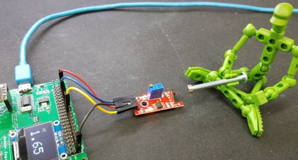
Image: Mo has moved the magnet close enough to the sensor to trip the threshold. Analog reading = 1.65V
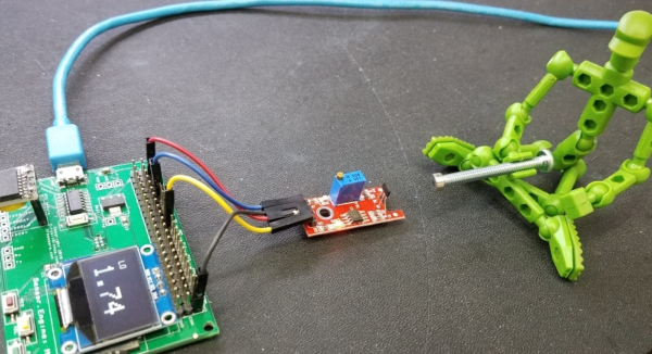
Image: Here Mo has moved the magnet away from the sensor. Voltage = 1.74V.
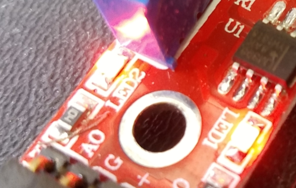
Image: LED 2 is illuminated since the magnet has tripped the threshold.
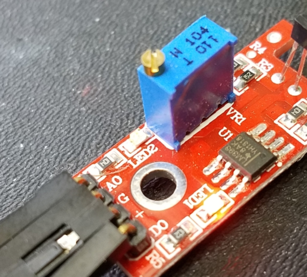
Image: With the magnet too far away the LED indicates that the value is lower than the threshold.
I gave him a small screwdriver and let Mo play with the variable potentiometer on this board. He was then able to change the voltage at which the threshold signal, and thus the LED, tripped.
If you have more information about certain modules, please feel free to Contact us! and share what you know. If you also have test or application code to share, that link is the way to share that - we would appreciate your experiences and input a lot!
If you are interested in purchasing the unique devices that are shown on these pages, CircuitGizmos (link: CircuitGizmosOnline) sells many of these devices. Also Tindie has several of the CircuitGizmos devices for sale.
If you have questions about sensor modules like these, consider joining the Facebook group. Join the 37 Sensors FB Group! We'd love to see you there. If you are interested in the CircuitGizmos products, the FB page to join is CircuitGizmos on FB
Sometimes the 37 sensor projects are described as Instructables. This is the Instructable user to follow: Indestructable and YouTube channel and even follow on Instagram. Link back to us, please! We really like learning how our products are used.
All content, not otherwise posted with a copyright notice, is Copyright 2017+ to the owner of 37sensors.com.