Analog Joystick
Analog Joystick (37 Sensors kit) Description
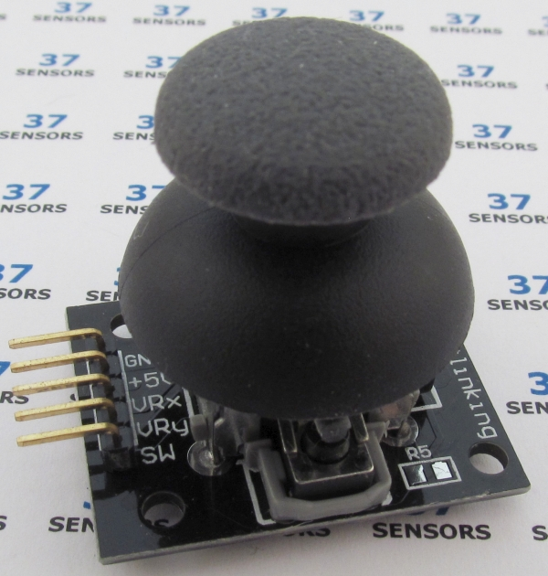
A joystick made from two potentiometers at right angles to each other. Analog output in both x and y directions. Push knob down for momentary switch. Knob included with the module.
Also called: joystick, mini dual axis joystick, KY023.
Found in kits: 37 sensors, 45 sensors.
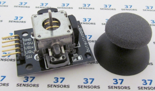
Image: Module with knob separated from dual potentiometer joystick.
Analog Joystick Specification/Notes:
• Voltage: 3.3V to 5.0V (No active components with voltage limits, so using other voltages are possible.)
• LED: none
• X Potentiometer: 10 k ohm, return-to-center (a few are 5 k ohm)
• Y Potentiometer: 10 k ohm, return-to-center (a few are 5 k ohm)
• Z switch: momentary SPST, pulled to +Voltage on some modules. Active low. Tactile.
• Size: 25mm X 35mm
There are a number of different sources for these modules. Not every module that looks similar to the ones here behaves exactly the same. Check the specific module that you have for differences in function, voltage levels, pinout, and inactive/active states. Some modules have been found to have incorrectly labeled pins and even poorly soldered components.
Button press (Z switch) is a bit difficult to do without making a substantial change to the X and Y values with the pots centered, and impossible with the pots in some positions. Joystick X and Y output should be close to half of the supply voltage when the joystick handle is centered (at rest).
The unpopulated R5 on the module tested would be the location for the pull-up resistor for the button. If needed, this can be populated with a 10kohm 0805 SMT resistor.
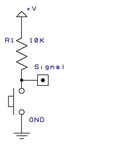
Image: Z-axis switch schematic.
Analog Joystick Module Pin-out:
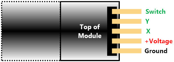
Image: Typical/common pinout. Always check the pinout for the module that you have.
Analog Joystick Test
Read of analog joystick with CGMICROKIT1, console display. This test uses two analog inputs to read the X and Y values, and a digital input to read the switch input every 200 milliseconds. The values for all three are printed out on the console.
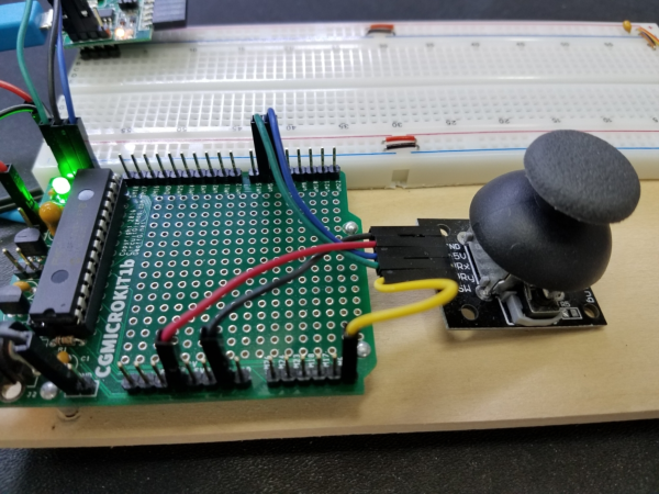
Image: CGMICROKIT1 to Analog Joystick.
• Black wire – Common ground
CGMICROKIT GND - Module Ground
• Red wire – Supply voltage
CGMICROKIT 3.3V - Module +Voltage
• Blue wire – Variable resistance X direction
CGMICROKIT uM4 (analog input) - Module X
• Green wire – Variable resistance Y direction
CGMICROKIT uM5 (analog input) - Module Y
• Yellow wire – Joystick press switch
CGMICROKIT uM6 (digital input) - Module Switch
SETPIN 6, DIN, PULLUP
SETPIN 4, AIN
SETPIN 5, AIN
DO
PAUSE 200
S = PIN(6)
X = PIN(4)
Y = PIN(5)
PRINT S, X, Y
LOOP
SETPIN 4, AIN
SETPIN 5, AIN
DO
PAUSE 200
S = PIN(6)
X = PIN(4)
Y = PIN(5)
PRINT S, X, Y
LOOP
Line 1-3: Set pin 6 to digital input with an internal pull-up resistor. Set pins 4 and 5 to analog input.
Line 5 and 11: Loop forever.
Line 6: Pause for 200 milliseconds.
Line 7: Read the switch input.
Line 8 and 9: Read the X and Y voltage values.
Line 10: Print the three values.
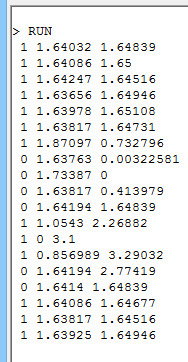
Image: Console output.
The output shows about 4 seconds of button pushing, X, and Y values.
Sensor.Engine: MICRO Analog Joystick test
Read of analog joystick with Sensor.Engine:MICRO, draw on display. This test uses two analog inputs to read the X and Y values displays the joystick position on the S.E:Micro display. Joystick switch press clears the display.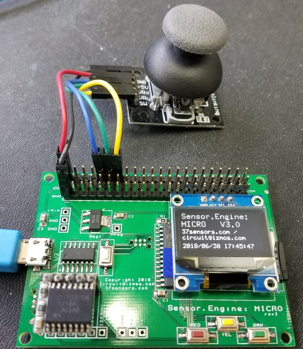
Image: Sensor.Engine:MICRO to Analog Joystick.
• Black wire – Common ground
Sensor.Engine:MICRO GND - Module Ground
• Red wire – Supply voltage
Sensor.Engine:MICRO 3.3V - Module +Voltage
• Blue wire – Variable resistance X direction
Sensor.Engine:MICRO P4 (analog input) - Module X
• Green wire – Variable resistance Y direction
Sensor.Engine:MICRO P5 (analog input) - Module Y
• Yellow wire – Joystick press switch
Sensor.Engine:MICRO P6 (digital input) - Module Switch
SETPIN 6, DIN, PULLUP
SETPIN 4, AIN
SETPIN 5, AIN
CLS
DO
S = PIN(6)
IF S = 0 THEN CLS
X = PIN(4)
Y = PIN(5)
PIXEL X*39, Y*20
LOOP
SETPIN 4, AIN
SETPIN 5, AIN
CLS
DO
S = PIN(6)
IF S = 0 THEN CLS
X = PIN(4)
Y = PIN(5)
PIXEL X*39, Y*20
LOOP
Line 1-3: Set pin 6 to digital input with an internal pull-up resistor. Set pins 4 and 5 to analog input.
Line 4: Clear screen initially.
Line 5 and 11: Loop forever.
Line 6: Read the switch input.
Line 7: If switch pressed (0), then clear display.
Line 8 and 9: Read the X and Y voltage values.
Line 10: Scale the values for the 128×64 display and plot the point.
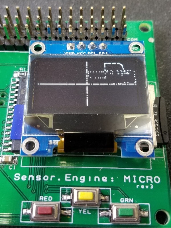
The OLED display immediately displayed a dot in the center of the screen because the joystick was centered in both the X and Y direction. The joystick was moved up and down, then side to side to make the straight lines. Finally, the joystick was moved around randomly in the upper right quadrant.
If you have more information about certain modules, please feel free to Contact us! and share what you know. If you also have test or application code to share, that link is the way to share that - we would appreciate your experiences and input a lot!
If you are interested in purchasing the unique devices that are shown on these pages, CircuitGizmos (link: CircuitGizmosOnline) sells many of these devices. Also Tindie has several of the CircuitGizmos devices for sale.
If you have questions about sensor modules like these, consider joining the Facebook group. Join the 37 Sensors FB Group! We'd love to see you there. If you are interested in the CircuitGizmos products, the FB page to join is CircuitGizmos on FB
Sometimes the 37 sensor projects are described as Instructables. This is the Instructable user to follow: Indestructable and YouTube channel and even follow on Instagram. Link back to us, please! We really like learning how our products are used.
All content, not otherwise posted with a copyright notice, is Copyright 2017+ to the owner of 37sensors.com.