Analog Temperature
Analog Temperature Description
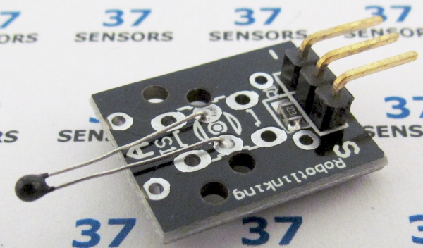
A thermistor used for temperature sensing. Analog output.
Also called: Temperature sensor, thermistor, KY013.
Found in kits: 37 sensors, 45 sensors.
Analog Temperature Specification/Notes:
• Voltage: 3.3V to 5.0V
• LED: Power (some modules)
• Size: 20mm X 15mm
• Room Temperature resistance: 10kohm
• Temperature range: -55°C – +125°C (+/- 0.5°C) -67°F – +257°F
There are a number of different sources for these modules. Not every module that looks similar to the ones here behaves exactly the same. Check the specific module that you have for differences in function, voltage levels, pinout, and inactive/active states. Some modules have been found to have incorrectly labeled pins and even poorly soldered components.
NTS temperature device. Connected in series with a 10kohm to use as a voltage divider circuit.
This device is NOT linear - a temperature change at a low temp will change the resistance at a higher temp a different amount. When the temperature increases, the resistance decreases.
Analog Temperature Module Pin-out:
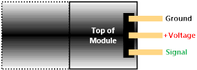
Image: Typical/common pinout. Always check the pinout for the module that you have.
Analog Temperature test
Read of analog temperature sensor with CGMICROKIT1, console display. This test uses an analog input to read the temperature values every 200 milliseconds. The value is printed out on the console.
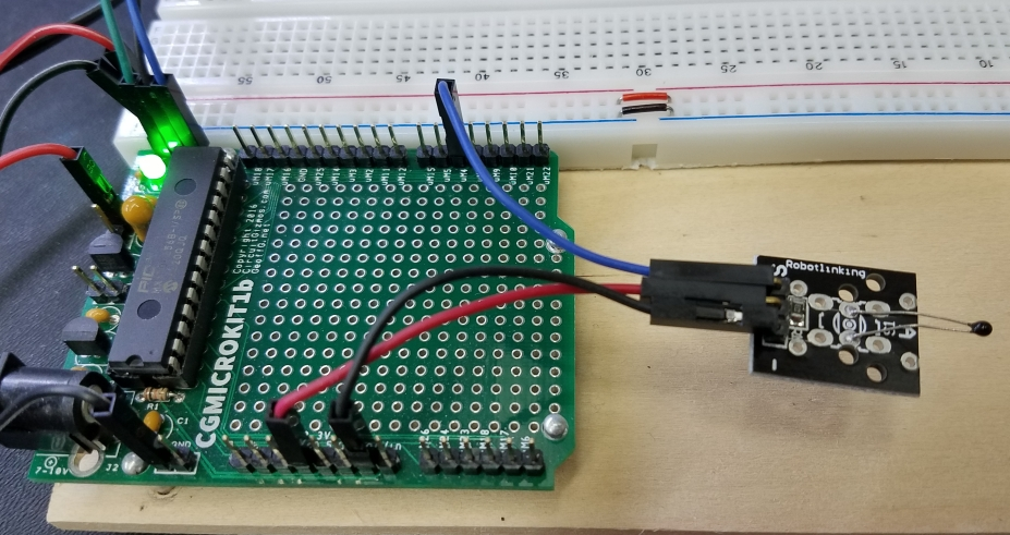
Image: Wiring the Analog Temperature Sensor to the CGMICROKIT1.
• Black wire – Common ground
CGMICROKIT GND - Module Ground
• Red wire – Supply voltage
CGMICROKIT 3.3V - Module +Voltage
• Blue wire – Analog temperature
CGMICROKIT uM4 (analog input) - Module temperature output
SETPIN 4, AIN
DO
PAUSE 200
X = PIN(4)
PRINT X
LOOP
DO
PAUSE 200
X = PIN(4)
PRINT X
LOOP
Line 1: Set pin 4 to analog input.
Line 3 and 7: Loop forever.
Line 4: Pause for 200 milliseconds.
Line 5: Read the analog input.
Line 6: Print the analog values.
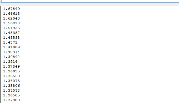
Image: Console output.
The output shows a couple of seconds of the sensor output at room temperature, then a drop in voltage as the temperature increases from touching the thermistor. There is a drop in the voltage as the temperature increases because this is a negative temperature coefficient thermistor. For this module and the default way to wire +Voltage and Ground, the resistor divider has the fixed resistor connected to +Voltage, and the variable resistor (the thermistor) connected to ground. The signal/voltage read is at the “middle” junction between the 10k fixed resistor and the thermistor.
Sensor.Engine: MICRO Analog Temperature Test
Read of analog temperature with Sensor.Engine:MICRO, console display. The same type of test as test 8 can be performed with a Sensor.Engine: MICRO. This test code utilizes the Steinhart-Hart equation to convert the measured voltage and known resistances to Kelvin, Celcius, and Fahrenheit.
SETPIN 4, AIN
DIM X as FLOAT
DIM R as FLOAT
DIM LOGR as FLOAT
DIM T AS FLOAT
DIM Tc AS FLOAT
DIM Tf AS FLOAT
DO
PAUSE 200
X = PIN(4)
R = 10000.0 / ((3.3 / X) - 1)
LOGR = log(R)
T = 1.0 / (0.001129148 + (0.000234125 + (0.0000000876741 * LOGR * LOGR ))* LOGR )
Tc = T - 273.15
Tf = (Tc * 9.0)/ 5.0 + 32.0
PRINT T, Tc, Tf
LOOP
Line 1: Set pin 4 to analog input.
Line 2-7: Set up floating point variables for measurements and calculations.
Line 9 and 18: Loop forever.
Line 10: Pause for 1/5 second. (5 readings per second)
Line 11: Read the input.
Line 12: Calculate the thermistor resistance.
Line 13 – 14: Steinhart-Hart calculations for degrees Kelvin.
Line 15: Conversion to Celcius.
Line 16: Conversion to Fahrenheit.
Line 15: Printing of all three temperature scales.
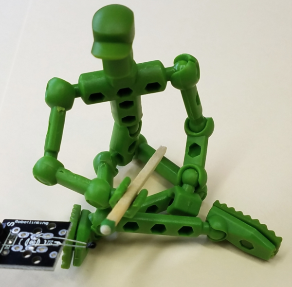
Image: My assistant Mo heating up the thermistor.
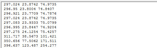
Image: Sensor output changing from room temperature to a nice toasty temperature.
You know, perhaps it wasn’t a great idea to give Mo matches. I keep smelling things burning.
Analog Temperature Test
Read of analog temperature sensor with Sensor.Engine:MICRO, output on LCD display. This test uses an analog input to read the temperature values every 200 milliseconds. This code also utilizes the Steinhart-Hart equation. A press of the green button flips between displaying C or F.
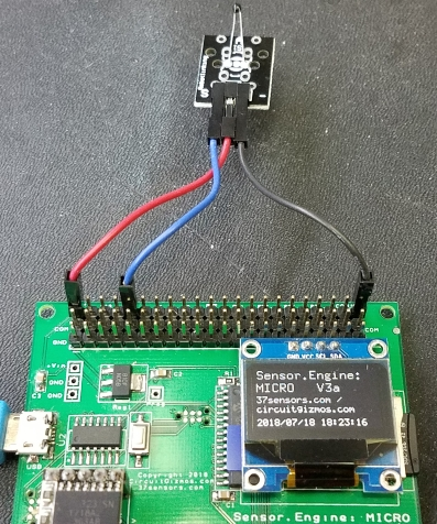
Image: Analog Temperature sensor wiring.
• Black wire – Common ground
Sensor.Engine:MICRO GND - Module Ground
• Red wire – Supply voltage
Sensor.Engine:MICRO 3.3V - Module +Voltage
• Blue wire – Analog temperature
Sensor.Engine:MICRO P4 (analog input) - Module temperature output
SETPIN 4, AIN
SETPIN 26, DIN, PULLUP
DIM X as FLOAT
DIM R as FLOAT
DIM LOGR as FLOAT
DIM T AS FLOAT
DIM Tc AS FLOAT
DIM Tf AS FLOAT
TCF = 0
DO
PAUSE 200
IF PIN(26) = 0 THEN TCF = TCF XOR 1
X = PIN(4)
R = 10000.0 / ((3.3 / X) - 1)
LOGR = log(R)
T = 1.0 / (0.001129148 + (0.000234125 + (0.0000000876741 * LOGR * LOGR ))* LOGR )
Tc = T - 273.15
Tf = (Tc * 9.0)/ 5.0 + 32.0
IF TCF = 1 THEN
TEXT 1,1,"Fahrenheit"
TEXT 10,30, STR$(Tf,1,2),,3,4
ELSE
TEXT 1,1,"Celcius "
TEXT 10,30, STR$(Tc,1,2),,3,4
ENDIF
LOOP
Line 1-2: Set pin 4 to analog input, pin 26 (green button) to digital input with internal pullup.
Line 3-8: Set up floating point variables for measurements and calculations.
Line 10: Set temperature display toggle to 0 (Celsius).
Line 12 and 28: Loop forever.
Line 13: Pause for 1/5 second. (5 readings per second)
Line 14: If pin happens to be pushed, toggle C/F.
Line 15: Read the input.
Line 16: Calculate the thermistor resistance.
Line 17 – 18: Steinhart-Hart calculations for degrees Kelvin.
Line 19: Conversion to Celsius.
Line 20: Conversion to Fahrenheit.
Line 21, 24, and 27: Print either C/F on LCD.
Line 22: Print “Fahrenheit” on LCD.
Line 23: Scale the values for the 128×64 display and print temperature in F.
Line 25: Print “Celsius” on LCD.
Line 26: Scale the values for the 128×64 display and print temperature in C.
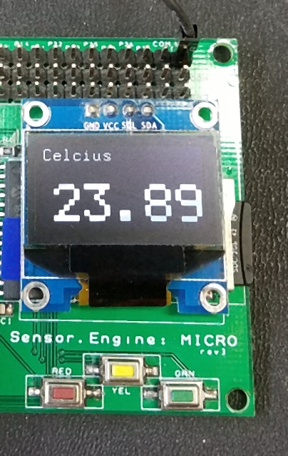
Image: Display showing room (lab) temperature in Celsius.
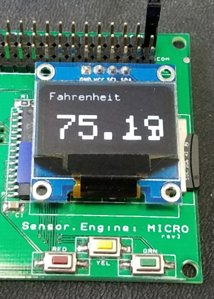
Image: Display showing room (lab) temperature in Fahrenheit.
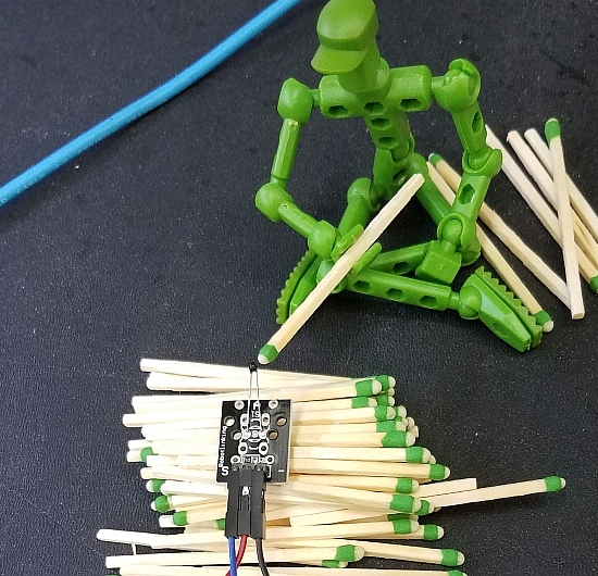
Image: Great. I let him play with matches once and my assistant becomes a pyromaniac.
No more matches for Mo.
If you have more information about certain modules, please feel free to Contact us! and share what you know. If you also have test or application code to share, that link is the way to share that - we would appreciate your experiences and input a lot!
If you are interested in purchasing the unique devices that are shown on these pages, CircuitGizmos (link: CircuitGizmosOnline) sells many of these devices. Also Tindie has several of the CircuitGizmos devices for sale.
If you have questions about sensor modules like these, consider joining the Facebook group. Join the 37 Sensors FB Group! We'd love to see you there. If you are interested in the CircuitGizmos products, the FB page to join is CircuitGizmos on FB
Sometimes the 37 sensor projects are described as Instructables. This is the Instructable user to follow: Indestructable and YouTube channel and even follow on Instagram. Link back to us, please! We really like learning how our products are used.
All content, not otherwise posted with a copyright notice, is Copyright 2017+ to the owner of 37sensors.com.