Relays and Drivers
Description
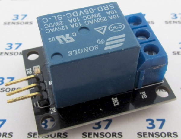
A driver circuit and single 5V relay that can control greater voltages/currents. Can make a direct connection to the microprocessor as this board has a relay driver circuit to drive the relay coil. Contacts typically rated for 10 amps.
Also called: relay, one channel relay, KY019.
Found in kits: 20 sensors, 37 sensors, 45 sensors.
Specification/Notes:
(Typical relay module)
• Voltage: 3.3V to 5.0V
• LED: Power
• Size: 20mm X 60mm
• Relay ratings are shown on the relay. Often 30VDC or 120VAC at greater the 5A.
• Typically SPST, NC/C/NO.
Some boards have a 1N4007 flyback diode for the relay’s coil.
May have activation LED. Transistor-driven with pulldown.
There are a number of different sources for these modules. Not every module that looks similar to the ones here behaves exactly the same. Check the specific module that you have for differences in function, voltage levels, pinout, and inactive/active states. Some modules have been found to have incorrectly labeled pins and even poorly soldered components.
Module Pin-out:
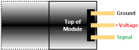
Image: Typical/common pinout. Always check the pinout for the module that you have.
Alternate Modules:
There are relay modules that are alternates to the one included in the 37 sensor kits. Some are mechanical relays, some are solid-state relays.
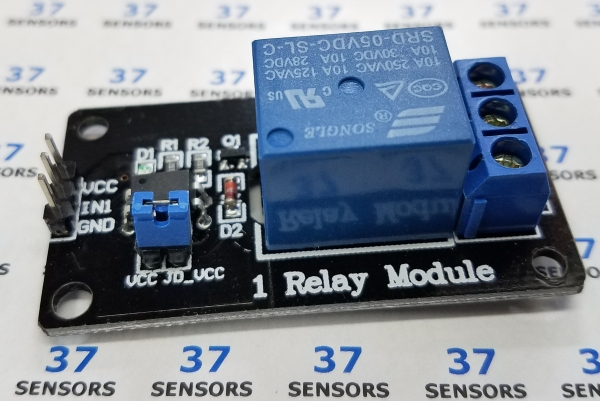
Image: Single 5V relay module. LED indicates operation. Relay operated from Vcc with the jumper in place, or from pin marked JD_VCC if the jumper is removed. Relay activated by grounding the signal input.
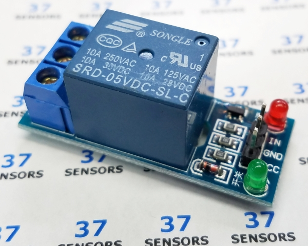
Image: Single 5V relay module. Red LED indicates power. Green LED indicates operation. Input at 5V operates the relay.
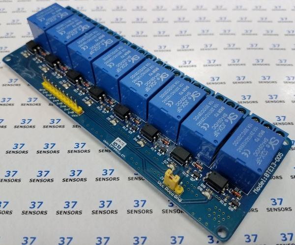
Image: Eight 5V relay module. Eight individual LEDs indicates operation. Relay operated from Vcc with the jumper in place, or from pin marked RVCC if the jumper is removed. Relay activated by grounding the signal input.
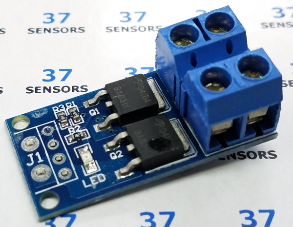
Image: Dual MOSFET PWM control module 400W 5V-36V. LED indicates operation.
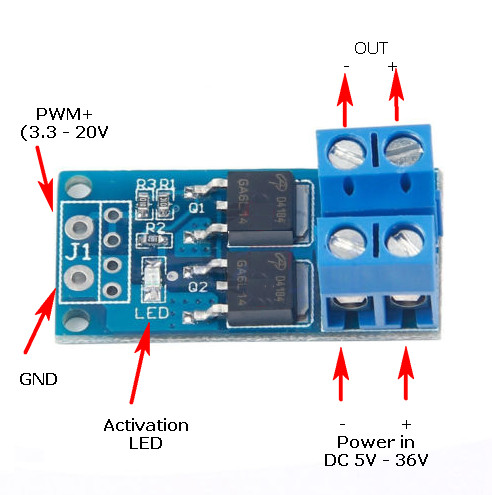
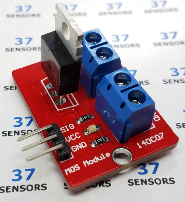
Image: IRF520-based solid-state relay. 3.3V-5V operation. LED indicates activation. Can drive 0-24V at 1 amp without a heat sink. Could drive up to 5 amps with a heat sink. Signal input at Vcc operates the relay.
For the IRF520 module, the pin connections are the logic-side (microcontroller) connections. Ground and VCC are the control circuit ground and +5V respectively. SIG is the activation line. Active is a high level (5V) and inactive is 0V.
(SIG can be driven at up to 10V to fully turn on the IRF520. Driving SIG at 5V actually only partially turns on the IRF520, and as a result it dissipates more heat.)
VIN and GND on the screw terminal is for the connection to the power supply (0-24V) on the driven side of the module. The V+ and V- connections on the other screw terminal are for the load. To drive a 12V incandescent lamp, for example, V+ and V- connect to the lamp. VIN would be 12V.
V+ and VIN are connected on the board.
IRF520 datasheet:
| Linked file: irf520ns.pdf |
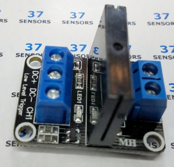
Image: Single 5V solid-state relay module. LED indicates operation. Input at 5V operates the relay. Can drive 240VAC at 2 amps.
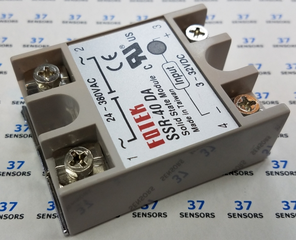
Image: Solid-state relay. 3-32VDC activation. LED indicates activation. Can control 24-380VAC at 40 amps.
Relay Test
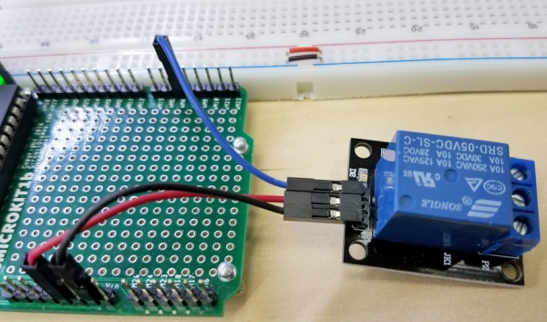
Image: CGMICROKIT1 to relay connections.
This is a very simple test that uses code to turn a relay on and off once each second repeatedly with a CGMICROKIT1. This test uses a digital output.
• Black wire – Common ground
CGMICRIOKIT GND - Module Ground
• Red wire – Supply voltage
CGMICROKIT 5V - Module +Voltage
• Blue wire – Relay input
CGMICROKIT uM4 (digital output) - Module relay control input
SETPIN 4, DOUT
DO
PIN(4) = 1
PAUSE 500
PIN(4) = 0
PAUSE 500
LOOP
DO
PIN(4) = 1
PAUSE 500
PIN(4) = 0
PAUSE 500
LOOP
Line 1: Set pin 4 to digital output.
Line 3 and 8: Loop forever.
Line 4: Set pin 4 high to turn the relay on.
Line 5: Pause for 500 milliseconds.
Line 6: Set pin 4 low to turn the relay off.
Line 7: Pause for 500 milliseconds.

Image: On, off, on, off, on, off…
Gif file:
| Linked file: clicky.gif |
Sensor.Engine: MICRO Relay Test
This test uses a relay board that has 8 relays. The software displays the relay status and allows for on/off control of any relay. The three buttons on the Sensor.Engine:MICRO will be used to select the relay (yellow), turn the relay off (red), and turn the relay on (green).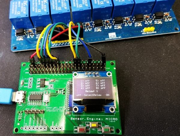
Image: Eight relay board connected to Sensor.Engine:MICRO
• Black wire – Common ground
• Sensor.Engine:MICRO GND - Module Ground
• Red wire – Supply voltage
• Sensor.Engine:MICRO 5V - Module +Voltage
• Blue/green/yellow wired – Relay input
Sensor.Engine:MICRO P4. P5, P6, P9, P10, P16, P21, P22 (digital outputs) - Module relay control inputs
SETPIN 4, DOUT
SETPIN 5, DOUT
SETPIN 6, DOUT
SETPIN 9, DOUT
SETPIN 10, DOUT
SETPIN 16, DOUT
SETPIN 21, DOUT
SETPIN 22, DOUT
SETPIN 7, INTL, RelayOff, PULLUP
SETPIN 24, INTL, IncRelay, PULLUP
SETPIN 26, INTL, RelayOn, PULLUP
R1 = 1
R2 = 1
R3 = 1
R4 = 1
R5 = 1
R6 = 1
R7 = 1
R8 = 1
Relay = 1
Text 0,00," 1) off 5) off ",,3,1
Text 0,10," 2) off 6) off ",,3,1
Text 0,20," 3) off 7) off ",,3,1
Text 0,30," 4) off 8) off ",,3,1
Text 0,57,"off SelectRelay ON",,3,1
DO
IF R1 = 0 THEN TEXT 36,00,"ON ",,3,1 ELSE TEXT 36,00,"off",,3,1
IF R2 = 0 THEN TEXT 36,10,"ON ",,3,1 ELSE TEXT 36,10,"off",,3,1
IF R3 = 0 THEN TEXT 36,20,"ON ",,3,1 ELSE TEXT 36,20,"off",,3,1
IF R4 = 0 THEN TEXT 36,30,"ON ",,3,1 ELSE TEXT 36,30,"off",,3,1
IF R5 = 0 THEN TEXT 96,00,"ON ",,3,1 ELSE TEXT 96,00,"off",,3,1
IF R6 = 0 THEN TEXT 96,10,"ON ",,3,1 ELSE TEXT 96,10,"off",,3,1
IF R7 = 0 THEN TEXT 96,20,"ON ",,3,1 ELSE TEXT 96,20,"off",,3,1
IF R8 = 0 THEN TEXT 96,30,"ON ",,3,1 ELSE TEXT 96,30,"off",,3,1
Text 36,42,"Relay: "+STR$(Relay),,3,1
PIN(4) = R1
PIN(5) = R2
PIN(6) = R3
PIN(9) = R4
PIN(10) = R5
PIN(16) = R6
PIN(21) = R7
PIN(22) = R8
LOOP
SUB IncRelay
Relay = Relay + 1
IF Relay = 9 THEN Relay = 1
END SUB
SUB RelayOff
IF Relay = 1 THEN R1 = 1
IF Relay = 2 THEN R2 = 1
IF Relay = 3 THEN R3 = 1
IF Relay = 4 THEN R4 = 1
IF Relay = 5 THEN R5 = 1
IF Relay = 6 THEN R6 = 1
IF Relay = 7 THEN R7 = 1
IF Relay = 8 THEN R8 = 1
END SUB
SUB RelayOn
IF Relay = 1 THEN R1 = 0
IF Relay = 2 THEN R2 = 0
IF Relay = 3 THEN R3 = 0
IF Relay = 4 THEN R4 = 0
IF Relay = 5 THEN R5 = 0
IF Relay = 6 THEN R6 = 0
IF Relay = 7 THEN R7 = 0
IF Relay = 8 THEN R8 = 0
END SUB
Line 1-8: Set pins that will operate the relays to digital output.
Line 10-12: Setup these pins with pull-up resistance and to call an interrupt subroutine when they go low. These are the Sensor.Engine:MICRO buttons.
Line 14-21: Rx is the relay state. The initial value is 1/high as the 8 relay module is active low.
Line 23: This is the selection index to the relays. The initial value is relay #1.
Line 25-29: Show default static text on the LCD.
Line 31 and 51: Loop forever.
Line 32-39: Test the relay state and display “off” or “ON” on the LCD.
Line 41: Display the selected relay number.
Line 43-50: Set the appropriate output pins for the relays.
Line 53-56: The IncRelay (increment relay value when yellow button pushed) subroutine.
Line 54: Increment the relay index. Valid range 1-8.
Line 55: Test for relay index at 9. If so, set back to 1.
Line 58-67: The RelayOff (turn selected relay off when red button pushed) subroutine.
Line 59-66: Set off state for the indexed relay.
Line 69-78: The RelayOn (turn selected relay on when red button pushed) subroutine.
Line 70-77: Set on state for the indexed relay.

Gif file:
| Linked file: 8relay.gif |
If you have more information about certain modules, please feel free to Contact us! and share what you know. If you also have test or application code to share, that link is the way to share that - we would appreciate your experiences and input a lot!
If you are interested in purchasing the unique devices that are shown on these pages, CircuitGizmos (link: CircuitGizmosOnline) sells many of these devices. Also Tindie has several of the CircuitGizmos devices for sale.
If you have questions about sensor modules like these, consider joining the Facebook group. Join the 37 Sensors FB Group! We'd love to see you there. If you are interested in the CircuitGizmos products, the FB page to join is CircuitGizmos on FB
Sometimes the 37 sensor projects are described as Instructables. This is the Instructable user to follow: Indestructable and YouTube channel and even follow on Instagram. Link back to us, please! We really like learning how our products are used.
All content, not otherwise posted with a copyright notice, is Copyright 2017+ to the owner of 37sensors.com.