Pinout
and Pin Use
Main Pinout
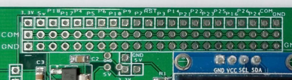
Image: Three rows of pins for the main SEM pinout
The Sensor.Engine:MICRO’s main pinout is along the top edge of the board. All of the interface signals are present here, with the exception of the console pins.
The very top row of printed circuit connections can be soldered to a 1 x 22 pin header (.1″ on center) extending down under the board that would then let the S.E:M be used with a solderless breadboard.
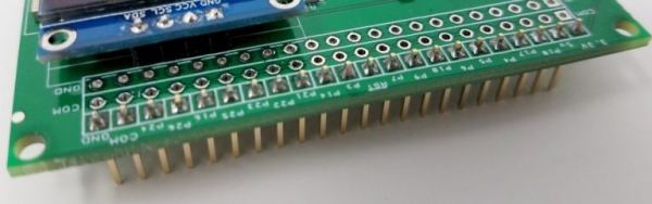
Image: Pin down option
As an alternative, the three rows of 22 connections could be populated with three 1×22 pin headers (either male or female) pointing upward to facilitate the use of single wire jumpers of appropriate gender to interface to various modules.
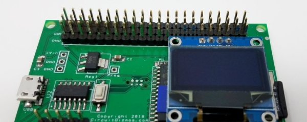
Image: Pin up option (older prototype board pictured)
The interface signals are on the row of 22 closest to the edge of the S.E:M.
Immediately behind that row is the “common” row. All connections on the common row are connected together and in common with the COM pin on the first row. The common row could be wired to 5V, 3.3V, or perhaps another voltage.
The third row (closest to the inside of the board) is ground.
First Row Pinout Table
| First Row pin | Function | |
|---|---|---|
| 1 | 3.3V | 3.3V Regulated |
| 2 | 5V | 5V (Directly connected to USB connector) |
| 3 | Pin 18 | I2C Data (RTC module) / Digital / Count (5V tolerant) |
| 4 | Pin 17 | I2C Clock (RTC module) / Digital / Count (5V tolerant) |
| 5 | Pin 4 | PWM 1a / Digital / Analog |
| 6 | Pin 5 | PWM 1b / Digital / Analog |
| 7 | Pin 6 | PWM 1c / Digital / Analog |
| 8 | Pin 10 | Com 2 Rx / Digital |
| 9 | Pin 9 | Com 2 Tx / Digital |
| 10 | Pin 7 | Com 1 Enable / Digital / Analog - Used onboard as RED button (contact to ground) |
| 11 | RESET | Resets the SEM microcontroller |
| 12 | Pin 3 | SPI_OUT. (Digital / Analog if SD card not used) |
| 13 | Pin 14 | SPI_IN. (Digital if SD card not used) (5V tolerant) |
| 14 | Pin 21 | Com 1 Tx / Digital (5v tolerant) |
| 15 | Pin 22 | Com 1 Rx / Digital (5v tolerant) |
| 16 | Pin 23 | SD card select. (Digital / Analog if SD card not used) |
| 17 | Pin 25 | SPI_CLK. (Digital / Analog if SD card not used) |
| 18 | Pin 16 | Wake / IR / Count / Digital (5v tolerant) |
| 19 | Pin 26 | PWM 2a / Digital / Analog - Used onboard as GREEN button (contact to ground) |
| 20 | Pin 24 | PWM 2b / Digital / Analog - Used onboard as YELLOW button (contact to ground) |
| 21 | COM | Connection to center common bus |
| 22 | GND | Ground |
Lower Connector Pinout
The lower pinouts on the Sensor.Engine:MICRO is a multipurpose output that allows for the attachment of serial devices (hardwired and wireless), IR decoders, I2C devices, and an RTC module.
Lower pinout
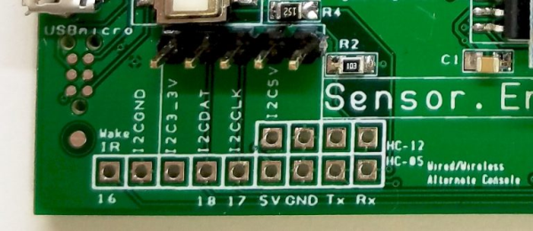
The SEM lower pinout has the console Tx and Rx signals of the SEM microcontroller. You can hardwire a TTL connection (see blue box) to the console serial port of the SEM. You can also connect to an HC-05 bluetooth module with the connections outlined in blue below. The red box on the image below is intended for direct wiring to an HC-12 half duplex radio module. In this way, the console connection to the SEM can be hardwired through a 3.3V TTL serial connection, or with the use of modules the console connection can be wireless.
The connections indicated below by the yellow box include 3.3V, ground, and a connection to pin 16. (Pin 16 is also on the main connector pinout as shown above.) Pin 16 can be used for remote wakeup (push button, for example) if the SEM processor is put to sleep, or it can be used to decode IR transmissions when connected to an IR demodulator. Left to right the pinout of signal, ground, and 3.3V matches that of a popular IR decoder.
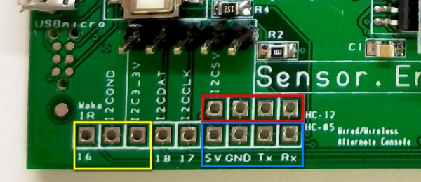
Image: IR decoder, radio, and bluetooth connections
The purple box below contains connections for I2C Data (pin 18) and Clock (pin 17) (duplicated from the main connector) and can be used for connecting to either 5V or 3.3V I2C devices. The 5 pin header in the orange box is intended to be used with the DS3231 Real-Time Clock module.
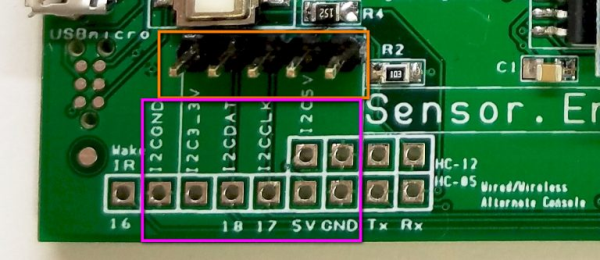
Image: RTC module header and optional I2C connections
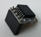
Image: The RTC module intended for use with the SEM
The RTC module is a DS3231 controller read via I2C bus. The module has a small battery located on the bottom of its little board so that time will continue running without being plugged in to the SEM, or when the SEM isn't powered.
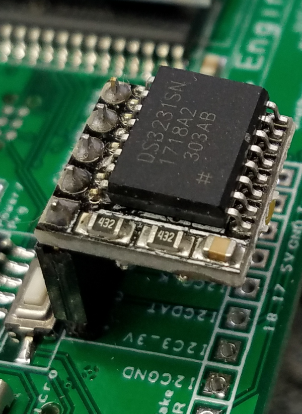
Image: RTC module in place
Solderless Breadboard Power Rail
When used with a solderless breadboard, the SEM can either get power from or provide power to the power rails. Ground and either 5V or 3.3V can connect from the SEM to the power rails.
Not all solderless breadboards are made the same. For some of the boards the holes that are a part of the power rail line up with the .1 inch on-center grid of the remainder of the breadboard.
With some solderless breadboards the holes of the power rails are not aligned with the rest of the board but are offset in both the X and Y directions. You had one job to do, solderless breadboard designer. You could have done better.
The SEM allows for both aligned and misaligned holes.
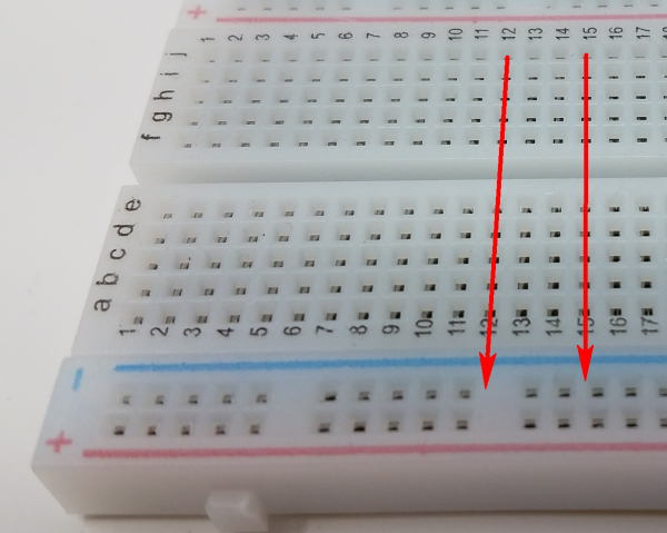
Image: Misaligned Holes
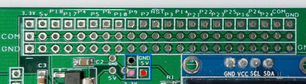
Image: Use these SEM power rail connections when the power rail lines up
The three square pad/holes (blue square) are for aligned power rails, and the three round pad/holes (orange square) are for the misaligned rails.
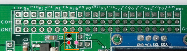
Image: Use these SEM power rail connections when the power rail is offset
A header pin belongs in the black ground position, while you should choose either the red/5V or the pink 3.3V for the power rail.
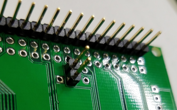
Image: In this case, the solderless breadboard power rails are the type that align with
the rest of the breadboard and ground (top) and 3.3V (bottom) are connected to the power rails
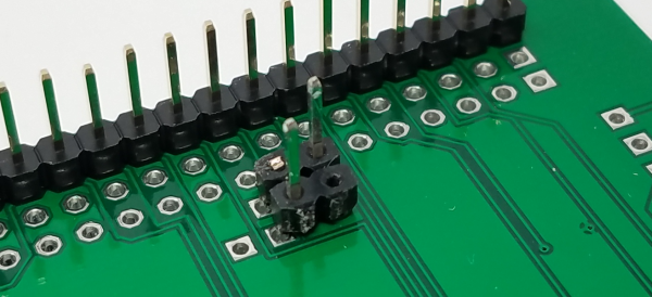
Image: In this case, the solderless breadboard power rails are the type that are
slightly offset from the rest of the breadboard and ground (top) and 3.3V (bottom)
are connected to the power rails
When the SEM is connected to the PC via USB, the SEM can provide the power rails of the solderless breadboard with ground and either 5V or 3.3V. Breadboard circuits can make use of the SEM as a source of power.
Or, if the solderless breadboard is powered, the rail power can be applied to the SEM. Please note, however, that then also connecting a USB cable could potentially pose a problem with two sources of 5V trying to power things.
These connections are optional as the power rails of the solderless breadboard could be connected in other ways. Ground should be connected in common.
Power Connector Pinout
As mentioned, power for the SEM can be provided through solderless bradboard power rails (see above), or via the 5V of the USB connection. This is likely the case for a SEM used for experimentation or development.
A SEM used as a stand alone controller, perhaps after developing the code for a certain purpose, can be powered through the power connection on the left side of the board.
Either a screw terminal or a pin header, as illustrated below, can be used to connect a regulated DC power supply of preferably 5V or 3.3V to the SEM. The center two pins are ground.
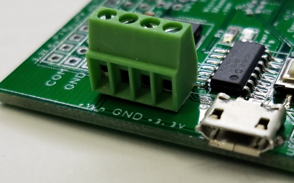
Image: Optional 4-position screw terminal for the power connection
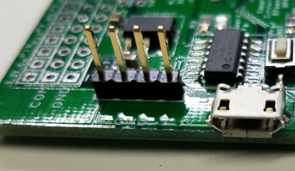
Image: Optional 4-position pin header for the power connection
If you have more information about certain modules, please feel free to Contact us! and share what you know. If you also have test or application code to share, that link is the way to share that - we would appreciate your experiences and input a lot!
If you are interested in purchasing the unique devices that are shown on these pages, CircuitGizmos (link: CircuitGizmosOnline) sells many of these devices. Also Tindie has several of the CircuitGizmos devices for sale.
If you have questions about sensor modules like these, consider joining the Facebook group. Join the 37 Sensors FB Group! We'd love to see you there. If you are interested in the CircuitGizmos products, the FB page to join is CircuitGizmos on FB
Sometimes the 37 sensor projects are described as Instructables. This is the Instructable user to follow: Indestructable and YouTube channel and even follow on Instagram. Link back to us, please! We really like learning how our products are used.
All content, not otherwise posted with a copyright notice, is Copyright 2017+ to the owner of 37sensors.com.