U401 USB Interface
The U401 is a USB solution that is pre-built, pre-programmed, and pre-tested and will get you interfacing your PC (Win⁄Linux) or Mac (OSX) to various devices in very little time! There is no USB device assembly, no driver development, and no firmware to write. In many cases, the U401 can be plugged into an experimenter’s breadboard and circuit interfacing can begin immediately. Demo software applications can be used “right out of the box”.
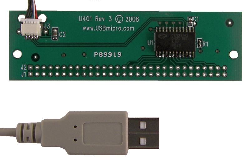
Image: Newest U401 (Rev 3) front view. This newest U401 has a lightweight and removable USB cable.
Features of the U401 USB Interface:
• USB Interface to PC (Win⁄Linux) or Mac (OSX)
• Uses HID Drivers Inherent in OS
• Sixteen I⁄O Lines
• SPI Master and Slave Communication
• LCD Interface Commands
• Stepper motor control
• 1-Wire Communication Interface
• Flexible Pin Use
• Free Compiled Sample Applications
• Visual Basic, C, Delphi Example Code Available
• Fully Assembled and Tested
• Great Replacement for Parallel Port Interfacing
• PC’s USB Power Brought to pins
• Easy to Use with Solderless Breadboards
• USB Cable Provided
Overview of the U401 USB Interface
Board Size: 3.5 inches (88.9 mm) long and 1.0 inches (25.4 mm) wide.
Computer Interface: USB
USB Cable Length: 36 inches (914 mm).
USB Connection type: Removable cable.
USB Power Type: Bus powered, uses the 5V provided by the USB interface.
Specified USB allowed current draw: 100 mA standard, total.
Bandwidth: 800 bytes per second as a HID device.
USB Bus Speed: 1.5 Mbits⁄s. (Low speed)
USB Driver: HID, part of the operating system.
Device Interface: 16 CMOS lines, selectable as inputs⁄outputs.
USB Cable Pin#, Color, Function Chart
| Pin Number | Wire Color | Function |
|---|---|---|
| 1 | Red | Vusb |
| 2 | White | D- |
| 3 | Green | D+ |
| 4 | Black | Ground⁄Shield |
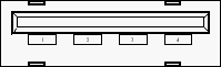
PC USB Port (Female ‘A’)
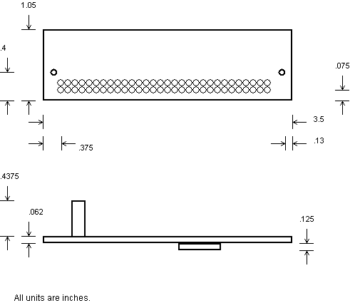
Board Layout:
Size and Clearance:
U401 Connector Pin Out
Main Connector:
Along the long edge of the board is the connector “J1”.
“J2” is immediately next to J1, and is connected one-to-one electrically.
| Pin Number | U401 Signal |
|---|---|
| 1 | <nc> (Pin 1 is located next to the silk screen “J1”.) |
| 2 | <nc> |
| 3 | <nc> |
| 4 | <nc> |
| 5 | <nc> |
| 6 | <nc> |
| 7 | +5V USB from PC |
| 8 | <nc> |
| 9 | GND |
| 10 | optional pull-up |
| 11 | optional pull-up |
| 12 | <nc> |
| 13 | <nc> |
| 14 | <nc> |
| 15 | PA.0 – Port A bit 0 (stepper motor control) |
| 16 | PA.1 – Port A bit 1 (stepper motor control) |
| 17 | PA.2 – Port A bit 2 (stepper motor control) (2-wire clock) |
| 18 | PA.3 – Port A bit 3 (stepper motor control) (2-wire data) |
| 19 | PA.4 – Port A bit 4 (stepper motor control) |
| 20 | PA.5 – Port A bit 5 (stepper motor control) |
| 21 | PA.6 – Port A bit 6 (stepper motor control) |
| 22 | PA.7 – Port A bit 7 (stepper motor control) |
| 23 | PB.0 – Port B bit 0 |
| 24 | PB.1 – Port B bit 1 |
| 25 | PB.2 – Port B bit 2 |
| 26 | PB.3 – Port B bit 3 |
| 27 | PB.4 – Port B bit 4 |
| 28 | PB.5 – Port B bit 5 |
| 29 | PB.6 – Port B bit 6 |
| 30 | PB.7 – Port B bit 7 |
Other Connectors:
J3 is the USB connection. J4 and J5 are for factory use.
Power Connection:
The +5V available on pin 7 is the power from the computer’s USB port. Up to 100mA can be drawn from this supply to power devices attached to the U401. If more power is needed, an external supply should be used to power additional circuits. Do not attach the +5V from an external supply to this pin. The ground connection should be common to any external power supply ground as well as any target circuits.
I2C Connection:
The pins labeled “SCL” and “SDA” are the I2C connections. On the U401 the connections are not made to the microcontroller. There are two unpopulated PCB positions for pull-up resistors for these lines. The I2C communication interface relies on a passive pull-up and an active pull-down. The positions can be populated with resistors if no other pull-up resistors exist on the I2C lines.
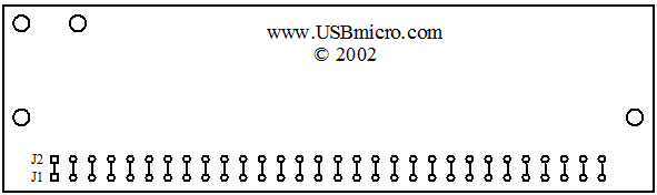
Board Layout:
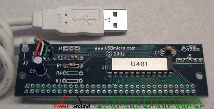
Image: The board above is an old version, but the pinout is the same for newer versions.
Note that all lines extend from J1 to J2. There are then some J1 lines that only connect to J2 and no other circuitry.

Image: Pin 1 on the U401 is located on the left, as you look at the board in the orientation above. Pin 30 is the pin on the far right.
If you have more information about certain modules, please feel free to Contact us! and share what you know. If you also have test or application code to share, that link is the way to share that - we would appreciate your experiences and input a lot!
If you are interested in purchasing the unique devices that are shown on these pages, CircuitGizmos (link: CircuitGizmosOnline) sells many of these devices. Also Tindie has several of the CircuitGizmos devices for sale.
If you have questions about sensor modules like these, consider joining the Facebook group. Join the 37 Sensors FB Group! We'd love to see you there. If you are interested in the CircuitGizmos products, the FB page to join is CircuitGizmos on FB
Sometimes the 37 sensor projects are described as Instructables. This is the Instructable user to follow: Indestructable and YouTube channel and even follow on Instagram. Link back to us, please! We really like learning how our products are used.
All content, not otherwise posted with a copyright notice, is Copyright 2017+ to the owner of 37sensors.com.