U421 USB Interface
The U421 is a USB solution that is pre-built, pre-programmed, and pre-tested and will get you interfacing your PC (Win⁄Linux) or Mac (OSX) to various devices in very little time! There is no USB device assembly, no driver development, and no firmware to write. In many cases, the U421 can be plugged into an experimenter’s breadboard and circuit interfacing can begin immediately. Demo software applications can be used “right out of the box”.
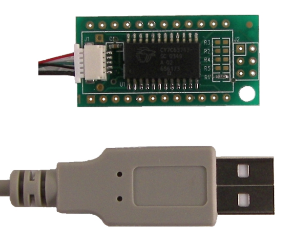
Image: U421 top view.
Features of the U421 USB Interface:
• USB Interface to PC
• Uses HID Drivers Inherent in OS
• Sixteen I⁄O Lines
• SPI Master and Slave Communication
• LCD Interface Commands
• Stepper motor control
• 1-Wire Communication Interface
• Flexible Pin Use
• Free Compiled Sample Applications
• Visual Basic, C, Delphi Example Code Available
• Fully Assembled and Tested
• Great Replacement for Parallel Port Interfacing
• PC’s USB Power Brought to Device
• Easy to Use with Solderless Breadboards
• USB Cable Provided
Overview of the U421 USB Interface
The U421 provides a simple digital i⁄o interface for the PC (Win⁄Linux) or Mac (OSX). Sixteen i⁄o lines from the microcontroller are provided. Commands can be sent to the U421 that change the i⁄o lines from input to output. I⁄o lines can be individually selected as inputs or outputs. The U421 supports commands to read the ports, and if the ports are set to output, to write to the ports.
The U421 is an interface to SPI (Serial Peripheral Interface) devices. SPI is a local synchronous serial bus that uses a clock line, two data lines, and a device select line for communication between a serial device and a host microcontroller. The firmware on the U421 provides generic access for reading and writing SPI devices. The SPI clock rate can be adjusted to 62.5 kHz, 500 kHz, 1 MHz, or 2 MHz. Because additional pins are available as generic i⁄o, the U421 can use these lines as slave select lines and address multiple SPI devices.
The SPI subsystem of the U421 can be used as a master to communicate with SPI devices such as EEPROMS and A⁄D converters. The U421 can also be used as a SPI slave to a microcontroller that uses the U421 as a gateway to the PC (Win⁄Linux) or Mac (OSX). A PIC, for example, can act as a SPI master to communicate data with the U421, which can then transfer the data to a PC (Win⁄Linux) or Mac (OSX) application. Most microcontrollers can communicate via SPI with software-driven routines, many have internal SPI hardware. SPI hardware is present on microcontrollers from little 8-bit devices, like the PIC, to 32-bit microcontrollers like the 680×0-based devices.
The U421 is a convenient way to interface a standard Hitachi-type of intelligent LCD controller to USB. The commands that support communication to the LCD module are the “standard” LCD commands. Standard commands include writing characters to the display and controlling the display.
The U421 is an assembled and tested circuit card that is 1.5 inches (38.1mm) long and 0.75 inches (19.1mm) wide. The U421 is a printed circuit board in a 24-pin “DIP-like” format.
The U421 interfaces to the PC (Win⁄Linux) or Mac (OSX) via the USB port. An application on the PC (Win⁄Linux) or Mac (OSX) controls the U421. The U421 does not use any custom drivers, just the drivers that are a part of the operating system. Custom software can be developed to use the U421, or the applications that have been created as examples here can also be used.
Uses for the U421 USB Interface
With the U421 you can utilize the USB port on your computer to interface with various electronic devices, such as lights, LCD displays, SPI analog and memory devices, switches, relays, tethered robots, model railroad control, and many custom circuits.
U421 Specifications
Board Size: 1.5 inches (38.1mm) long and 0.75 inches (19.1mm) wide.
Board Type: 24-pin PCB in a “DIP-like” format, rows spaced .6″ (15.2mm) apart.
Computer Interface: USB
USB Cable Length: 36 inches (914 mm).
USB Connection type: Removable cable.
USB Power Type: Bus powered, uses the 5V provided by the USB interface.
Specified USB allowed current draw: 100mA standard, total.
Bandwidth: 800 bytes per second as a HID device.
USB Bus Speed: 1.5Mbits⁄s. (Low speed)
USB Driver: HID, part of the operating system.
Device Interface: 16 CMOS lines, selectable as inputs⁄outputs.
USB Cable Pin#, Color, Function Chart
| Pin Number | Wire Color | Function |
|---|---|---|
| 1 | Red | Vusb |
| 2 | White | D- |
| 3 | Green | D+ |
| 4 | Black | Ground⁄Shield |
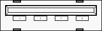
PC USB Port (Female ‘A’)
Board Layout:

U421 PCB Pin Out
“DIP-like” Connector:
| Pin Number | U421 Signal |
|---|---|
| 1 | PA.0 – Port A bit 0 (stepper motor control) |
| 2 | PA.1 – Port A bit 1 (stepper motor control) |
| 3 | PA.2 – Port A bit 2 (stepper motor control) (2-wire clock) |
| 4 | PA.3 – Port A bit 3 (stepper motor control) (2 wire data) |
| 5 | PB.0 – Port B bit 0 |
| 6 | PB.2 – Port B bit 2 |
| 7 | PB.4 – Port B bit 4 |
| 8 | PB.6 – Port B bit 6 |
| 9 | Ground |
| 10 | No Connect |
| 11 | No Connect |
| 12 | Do not use |
| 13 | No Connect |
| 14 | +5V (USB) |
| 15 | USB D- (already connected to the USB cable) |
| 16 | USB D+ (already connected to the USB cable) |
| 17 | PB.7 – Port B bit 7 |
| 18 | PB.5 – Port B bit 5 |
| 19 | PB.3 – Port B bit 3 |
| 20 | PB.1 – Port B bit 1 |
| 21 | PA.7 – Port A bit 7 (or SPI SCK) (stepper motor control) |
| 22 | PA.6 – Port A bit 6 (or SPI MISO) (stepper motor control) |
| 23 | PA.5 – Port A bit 5 (or SPI MOSI) (stepper motor control) |
| 24 | PA.4 – Port A bit 4 (or SPI SS [when in slave mode]) (stepper motor control) |
Power Connection:
The +5V available on pin 14 is the power from the computer’s USB port. Up to 100mA can be drawn from this supply to power devices attached to the U421. If more power is needed, an external supply should be used to power additional circuits. Do not attach the +5V from an external supply to this pin. The ground connection should be common to any external power supply ground as well as any target circuits.
Board Layout:
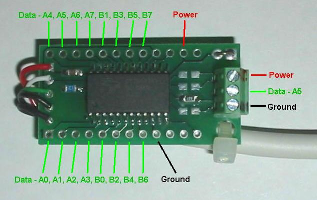
Image: (U421-SC3 screw terminal version of the U421 no longer available)
A standard U421 does not have the screw terminal.
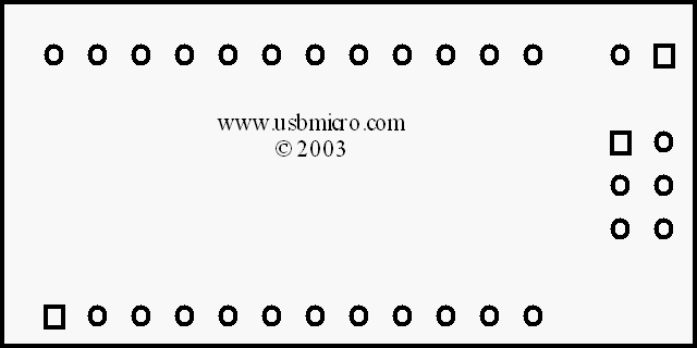
Image: Pin 1 on the U421 is located on the lower left, as you look at the board in the orientation above. Pin 24 is the pin on the upper left. The lower row, therefore, is 1-12, the upper row is 24-13.
If you have more information about certain modules, please feel free to Contact us! and share what you know. If you also have test or application code to share, that link is the way to share that - we would appreciate your experiences and input a lot!
If you are interested in purchasing the unique devices that are shown on these pages, CircuitGizmos (link: CircuitGizmosOnline) sells many of these devices. Also Tindie has several of the CircuitGizmos devices for sale.
If you have questions about sensor modules like these, consider joining the Facebook group. Join the 37 Sensors FB Group! We'd love to see you there. If you are interested in the CircuitGizmos products, the FB page to join is CircuitGizmos on FB
Sometimes the 37 sensor projects are described as Instructables. This is the Instructable user to follow: Indestructable and YouTube channel and even follow on Instagram. Link back to us, please! We really like learning how our products are used.
All content, not otherwise posted with a copyright notice, is Copyright 2017+ to the owner of 37sensors.com.