U451 USB Relay Interface
The U451 is a USB solution that is pre-built, pre-programmed, and pre-tested and will get you interfacing your PC (Win⁄Linux) or Mac (OSX) to various devices in very little time! There is no USB device assembly, no driver development, and no firmware to write. Demo software applications can be used “right out of the box”.
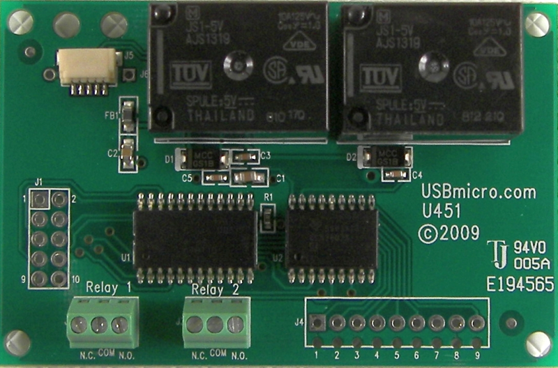
Image: U451 top view.
Features of the U451 USB Relay Interface
• Two Form-C relays rated at 125 volts, 10 amp
• Six 500mA switch-to-ground outputs on J4
• Firmware functions compatible with U401⁄U421
• U401⁄U421 Port 0 functions available on J1
• USB Interface to PC
• Uses HID Drivers Inherent in OS
• SPI Master and Slave Communication
• Stepper motor control
• 1-Wire Communication Interface
• Flexible Pin Use
• Free Compiled Sample Applications
• Visual Basic, C, Delphi Example Code Available
• Fully Assembled and Tested
• Great Replacement for Parallel Port Interfacing
• PC’s USB Power Brought to Device
• USB Cable Provided
Overview of the U451 USB Interface
The U451 provides a simple digital i⁄o interface for the PC (Win⁄Linux) or Mac (OSX). Two relays, six transistor outputs, and eight i⁄o lines from the microcontroller are provided. Commands can be sent to the U451 that change the eight i⁄o lines from input to output. I⁄O lines can be individually selected as inputs or outputs. The U451 supports commands to read the ports, and if the ports are set to output, to write to the ports.
The U451 has all of the firmware features of the U401 and U421.
The U451 is an assembled and tested circuit card that is 2.8125 inches (72mm) long and 1.625 inches (47mm) wide. The U451 has 4 mounting holes.
The U451 interfaces to the PC (Win⁄Linux) or Mac (OSX) via the USB port. An application on the PC (Win⁄Linux) or Mac (OSX) controls the U451. The U451 does not use any custom drivers, just the drivers that are a part of the operating system. Custom software can be developed to use the U451, or the applications that have been created as examples here can also be used.
Uses for the U451 USB Relay Interface
With the U451 you can utilize the USB port on your computer to interface with various electronic devices, such as lights, LCD displays, SPI analog and memory devices, switches, relays, tethered robots, model railroad control, and many custom circuits. PCB trace widths limit the connections to the relays to about two amps – this should not be exceeded.
U451 Specifications
Board Size: 1.5 inches (38.1 mm) long and 0.75 inches (19.1 mm) wide.
Computer Interface: USB
USB Cable Length: 36 inches (914 mm).
USB Connection type: Removable cable.
USB Power Type: Bus powered, uses the 5V provided by the USB interface.
Specified USB allowed current draw: 100 mA standard, total.
Bandwidth: 800 bytes per second as a HID device.
USB Bus Speed: 1.5 Mbits⁄s. (Low speed)
USB Driver: HID, part of the operating system.
Device Interface: 2 form-C relays (125V – 10A), 6 Darlington outputs (500 mA), 8 CMOS lines selectable as inputs⁄outputs. Because of trace width, currents should be limited to 2 amps.
U451 PCB Pin Out
Relay 1 Connector:
| Pin Name | Description |
|---|---|
| N.C. | Normally Closed. When relay 1 is not activated, the common terminal connects to N.C. Relay 1 is Port B bit 0. |
| COM | Common. This connects to N.C. when relay 1 is not energized, and switches to N.O. when it is. |
| N.O. | Normally Open. When relay 1 is activated, the common terminal connects to N.O. |
Relay 2 Connector:
| Pin Name | Description |
|---|---|
| N.C. | Normally Closed. When relay 2 is not activated, the common terminal connects to N.C. Relay 1 is Port B bit 1 |
| COM | Common. This connects to N.C. when relay 2 is not energized, and switches to N.O. when it is. |
| N.O. | Normally Open. When relay 2 is activated, the common terminal connects to N.O. |
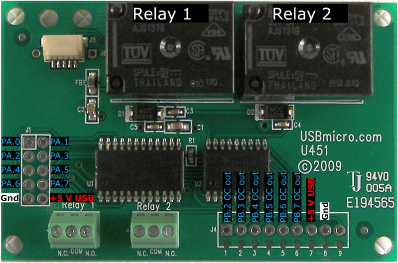
J4 Connector:
| Pin Number | Signal |
|---|---|
| 1 | PB.2 – Port B bit 2 driving a Darlington transistor to ground (a high sent to this port line pulls the pin to ground) |
| 2 | PB.3 – Port B bit 3 driving a Darlington transistor to ground (a high sent to this port line pulls the pin to ground) |
| 3 | PB.4 – Port B bit 4 driving a Darlington transistor to ground (a high sent to this port line pulls the pin to ground) |
| 4 | PB.5 – Port B bit 5 driving a Darlington transistor to ground (a high sent to this port line pulls the pin to ground) |
| 5 | PB.6 – Port B bit 6 driving a Darlington transistor to ground (a high sent to this port line pulls the pin to ground) |
| 6 | PB.7 – Port B bit 7 driving a Darlington transistor to ground (a high sent to this port line pulls the pin to ground) |
| 7 | +5V (USB) |
| 8 | Ground |
| 9 | Common for Darlington. Optionally connect to external voltage. |
J1 Connector:
| Pin Number | Signal |
|---|---|
| 1 | PA.0 – Port A bit 0 (stepper motor control) |
| 2 | PA.1 – Port A bit 1 (stepper motor control) |
| 3 | PA.2 – Port A bit 2 (stepper motor control) (2-wire clock) |
| 4 | PA.3 – Port A bit 3 (stepper motor control) (2-wire data) |
| 5 | PA.4 – Port A bit 4 (or SPI SS when in slave mode ) (stepper motor control) |
| 6 | PA.5 – Port A bit 5 (or SPI MOSI) (stepper motor control) |
| 7 | PA.6 – Port A bit 6 (or SPI MISO) (stepper motor control) |
| 8 | PA.7 – Port A bit 7 (or SPI SCK) (stepper motor control) |
| 9 | Ground |
| 10 | +5V (USB) |
Power Connection:
The +5V available is the power from the computer’s USB port. Up to 100mA can be drawn from this supply to power devices attached to the U451. If more power is needed, an external supply should be used to power additional circuits. Do not attach the +5V from an external supply to this pin. The ground connection should be common to any external power supply ground as well as any target circuits.
Relay Activation:
The two port lines that connect to the relays need to be set to output. PB.0 activates relay 1 when set to high, and PB.1 activates relay 2 when set to a high.
Board Layout:
If you have more information about certain modules, please feel free to Contact us! and share what you know. If you also have test or application code to share, that link is the way to share that - we would appreciate your experiences and input a lot!
If you are interested in purchasing the unique devices that are shown on these pages, CircuitGizmos (link: CircuitGizmosOnline) sells many of these devices. Also Tindie has several of the CircuitGizmos devices for sale.
If you have questions about sensor modules like these, consider joining the Facebook group. Join the 37 Sensors FB Group! We'd love to see you there. If you are interested in the CircuitGizmos products, the FB page to join is CircuitGizmos on FB
Sometimes the 37 sensor projects are described as Instructables. This is the Instructable user to follow: Indestructable and YouTube channel and even follow on Instagram. Link back to us, please! We really like learning how our products are used.
All content, not otherwise posted with a copyright notice, is Copyright 2017+ to the owner of 37sensors.com.