RGB
LED
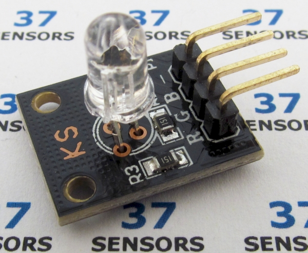
Image: RGB LED module, through-hole (150 ohm current limiting resistors)
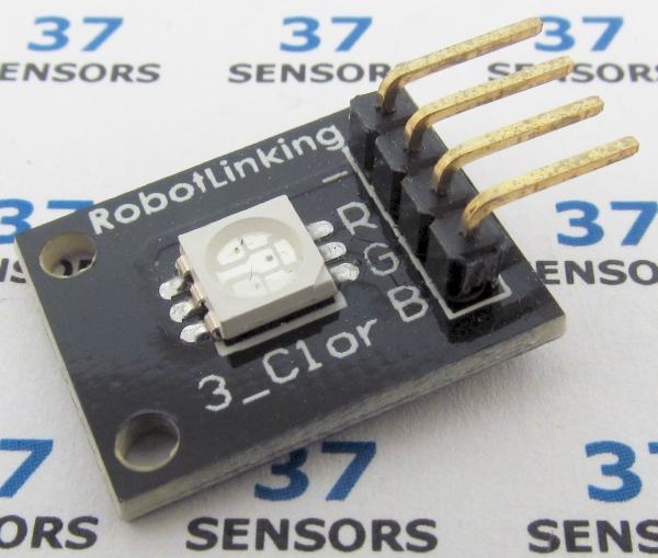
Image: RGB LED module, surface mount 5050 Note that there are no current limiting resistors on this module.
Description
LED containing red, green, and blue emitters, each controlled independently. Some modules have current limiting resistors, some do not.
Also called: full color LED, three color LED, tri-chromatic LED, KY021, KY016.
Found in kits: 37 sensors, 45 sensors (through-hole LED).
Found in kits: 20 sensors, 37 sensors, 45 sensors (SMT LED).
Specification/Notes:
• LED: Either TH (5mm) or SMT 5050
• Current: under 20mA typical per LED
• Forward voltage drop red: 2.1V
• Forward voltage drop green: 3.2V
• Forward voltage drop blue: 3.2
• Red: 625nm
• Green: 530nm
• Blue: 465nm
• Size: 20mm X 15mm
Some modules have current limiting resistors, some do not. The typical resistance value is 120 – 330 Ohms. The three LED dice internal to the package are common cathode.
Pins are frequently labeled incorrectly. RGB, BGR, GRB, etc.
There are a number of different sources for these modules. Not every module that looks similar to the ones here behaves exactly the same. Check the specific module that you have for differences in function, voltage levels, pinout, and inactive/active states. Some modules have been found to have incorrectly labeled pins and even poorly soldered components.
Module Pin-out:
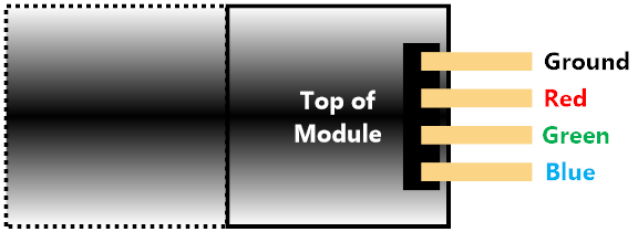
Image: Typical/common pinout. Always check the pinout for the module that you have.
If you have more information about certain modules, please feel free to Contact us! and share what you know. If you also have test or application code to share, that link is the way to share that - we would appreciate your experiences and input a lot!
If you are interested in purchasing the unique devices that are shown on these pages, CircuitGizmos (link: CircuitGizmosOnline) sells many of these devices. Also Tindie has several of the CircuitGizmos devices for sale.
If you have questions about sensor modules like these, consider joining the Facebook group. Join the 37 Sensors FB Group! We'd love to see you there. If you are interested in the CircuitGizmos products, the FB page to join is CircuitGizmos on FB
Sometimes the 37 sensor projects are described as Instructables. This is the Instructable user to follow: Indestructable and YouTube channel and even follow on Instagram. Link back to us, please! We really like learning how our products are used.
Sensor.Engine:MICRO RGB module test
This test is set up with a Sensor.Engine MICRO, the module (through-hole LED), and some jumper wires place on a solderless breadboard. The code is downloaded to the S.E.M. from a PC.
This test blinks the red, green, and blue elements of the RGB LED.
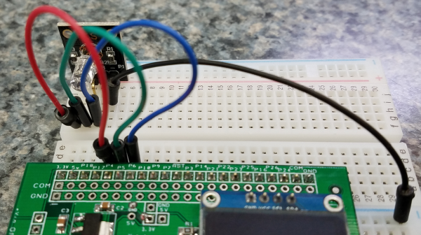
Image: Wiring the RGB LED to a SEM.
Black wire – Common ground, SEM GND - Module Ground
Red wire – RedLED element, SEM P4 - Module R
Green wire – RedLED element, SEM P5 - Module G
Blue wire – RedLED element, SEM P6 - Module B
This particular through-hole LED module has a current limiting resistor so no external resistor needed. The SMT RGB LED could also be used, but current-limiting resistors would be needed.
' Set direction for the pins to output
SETPIN 4, DOUT
SETPIN 5, DOUT
SETPIN 6, DOUT
' Repeat forever
DO
' Set each pin high, then low with delays
PAUSE 200 : PIN(4) = 1 : PAUSE 200 : PIN(4) = 0
PAUSE 200 : PIN(5) = 1 : PAUSE 200 : PIN(5) = 0
PAUSE 200 : PIN(6) = 1 : PAUSE 200 : PIN(6) = 0
LOOP
SETPIN 4, DOUT
SETPIN 5, DOUT
SETPIN 6, DOUT
' Repeat forever
DO
' Set each pin high, then low with delays
PAUSE 200 : PIN(4) = 1 : PAUSE 200 : PIN(4) = 0
PAUSE 200 : PIN(5) = 1 : PAUSE 200 : PIN(5) = 0
PAUSE 200 : PIN(6) = 1 : PAUSE 200 : PIN(6) = 0
LOOP
Code: RGB module test code in MMBasic to blink each LED color.
RGB
module test results
Image: Animated .gif
| Linked file: 20190322_213036.gif |
r = 1
g = 1
b = 100
PWM 1, 1000, r, g, b
PAUSE 5000
DO
for r = 0 to 99 STEP 2
PWM 1, 1000, r, g, b
PAUSE 10
NEXT r
PAUSE 5000
for b = 100 to 1 STEP -2
PWM 1, 1000, r, g, b
PAUSE 10
NEXT b
PAUSE 5000
for g = 0 to 99 STEP 2
PWM 1, 1000, r, g, b
PAUSE 10
NEXT g
PAUSE 5000
for r = 100 to 1 STEP -2
PWM 1, 1000, r, g, b
PAUSE 10
NEXT r
PAUSE 5000
for b = 0 to 99 STEP 2
PWM 1, 1000, r, g, b
PAUSE 10
NEXT b
PAUSE 5000
for g = 100 to 1 STEP -2
PWM 1, 1000, r, g, b
PAUSE 10
NEXT g
PAUSE 5000
LOOP
Code: RGB module test code in MMBasic using PWM
This test code uses PWM to slowly increase/decrease the output of the R, G, and B channels in patterns. There are 5 second delays between the changes.
The PWM outputs can be run through a solid state relay (see relay page) or a FET to drive 5V or 12V RGB LED strips.
On Instructables: https://www.instructables.com/id/Using-RGB-LED-From-37-Sensors-Kit/
USBmicro
U4xx
RGB
module test
This test is set up with the U401 to blink the red, green, and blue elements of the RGB LED. The USBmicro U401 connects to a computer using USB and can be controlled in several languages running on the computer. The PC controls the U401.
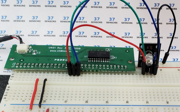
Image: U401 and RGB module test wiring.
Black wire – Common ground, U4xx Ground
Red wire – RedLED element, U4xx A0 - Module R
Green wire – RedLED element, U4xx A1 - Module G
Blue wire – RedLED element, U4xx A2 - Module B
#INCLUDE ONCE "USBmDLL.inc"
Dim workstr As String * 255
Dim result As Integer
DIm PortAval as byte
'------------------------------------------------------------------------------
'thinAir Visual Designer
'------------------------------------------------------------------------------
'---Needed thinBasic modules
USES "UI"
'---Controls IDs---
Begin ControlID
%IDC_CHECKBOX_RED
%IDC_CHECKBOX_GREEN
%IDC_CHECKBOX_BLUE
%IDC_EDIT_2
End ControlID
' Public this
DIM hDlg As Long
'------------------------------------------------------------------------------
' Main thinBasic function
'------------------------------------------------------------------------------
Function TBMain() As Long
MainWindow_Create(%HWND_DESKTOP)
End Function
'------------------------------------------------------------------------------
' Create main Window
'------------------------------------------------------------------------------
Function MainWindow_Create(ByVal hParent As Long) As Long
'Local hDlg As Long
Local hFont As Long
Local lStyle As Long
Local lStyleEx As Long
lStyle = _
%WS_DLGFRAME | _
%WS_CAPTION | _
%WS_SYSMENU | _
%WS_OVERLAPPEDWINDOW | _
%WS_CLIPCHILDREN | _
%WS_CLIPSIBLINGS | _
%DS_CENTER
lStyleEx = 0
Dialog New Pixels, hParent, "RGB1", -1, -1, 463, 240, lStyle, lStyleEx, TO hDlg
hFont = Font_Create("MS Sans Serif", 8)
Dialog Send hDlg, %WM_SETFONT, hFont, 0
CONTROL ADD CHECKBOX, hDlg, %IDC_CHECKBOX_RED, "Red", 8, 160, 56, 24, %WS_CHILD OR %WS_CLIPSIBLINGS OR %WS_TABSTOP OR %WS_VISIBLE OR %BS_AUTOCHECKBOX, 0
CONTROL ADD CHECKBOX, hDlg, %IDC_CHECKBOX_GREEN, "Green", 8, 184, 56, 24, %WS_CHILD OR %WS_CLIPSIBLINGS OR %WS_TABSTOP OR %WS_VISIBLE OR %BS_AUTOCHECKBOX, 0
CONTROL ADD CHECKBOX, hDlg, %IDC_CHECKBOX_BLUE, "Blue", 8, 208, 56, 24, %WS_CHILD OR %WS_CLIPSIBLINGS OR %WS_TABSTOP OR %WS_VISIBLE OR %BS_AUTOCHECKBOX, 0
CONTROL ADD TEXTBOX, hDlg, %IDC_EDIT_2, "", 8, 8, 448, 144, %WS_CHILD OR %WS_CLIPSIBLINGS OR %WS_TABSTOP OR %WS_VISIBLE or %ES_MULTILINE, %WS_EX_CLIENTEDGE or %ES_MULTILINE
' Display DLL info
workstr = ""
USBm_About(workstr)
CONTROL APPEND TEXT hDlg, %IDC_EDIT_2, "DLL Info: " + workstr
CONTROL APPEND TEXT hDlg, %IDC_EDIT_2, CRlf
workstr = ""
USBm_Version(workstr)
CONTROL APPEND TEXT hDlg, %IDC_EDIT_2, "DLL Ver: " + workstr
CONTROL APPEND TEXT hDlg, %IDC_EDIT_2, CRlf
workstr = ""
USBm_Copyright(workstr)
CONTROL APPEND TEXT hDlg, %IDC_EDIT_2, "DLL Copyright: " + workstr
CONTROL APPEND TEXT hDlg, %IDC_EDIT_2, CRlf
USBm_FindDevices()
result = USBm_NumberOfDevices()
CONTROL APPEND TEXT hDlg, %IDC_EDIT_2, "Number of devices: " + STR$(result)
CONTROL APPEND TEXT hDlg, %IDC_EDIT_2, CRlf
USBm_DirectionAOut(0)
PortAval = 0
USBm_WriteA(0,PortAval)
Dialog Show Modal hDlg, CALL MainWindow_Proc
Win_DeleteObject hFont
End Function
'------------------------------------------------------------------------------
' Main WIndow CallBack handler
'------------------------------------------------------------------------------
CallBack Function MainWindow_Proc() As Long
LOCAL pNMHDR AS NMHDR PTR
LOCAL PageNo AS LONG
LOCAL hFontTab AS LONG
Local RedState as long
Local GreenState as long
Local BlueState as long
SELECT CASE (CBMSG)
CASE %WM_INITDIALOG
CASE %WM_COMMAND
SELECT CASE LOWRD(CBWPARAM)
CASE %IDOK
CASE %IDCANCEL
END SELECT
CASE %WM_NOTIFY
CONTROL GET CHECK hDlg, %IDC_CHECKBOX_RED TO RedState
CONTROL GET CHECK hDlg, %IDC_CHECKBOX_GREEN TO GreenState
CONTROL GET CHECK hDlg, %IDC_CHECKBOX_BLUE TO BlueState
If RedState = 1 then
PortAval = BIT_Set(PortAval, 0)
else
PortAval = BIT_reSet(PortAval, 0)
endif
If GreenState = 1 then
PortAval = BIT_Set(PortAval, 1)
else
PortAval = BIT_reSet(PortAval, 1)
endif
If BlueState = 1 then
PortAval = BIT_Set(PortAval, 2)
else
PortAval = BIT_reSet(PortAval, 2)
endif
USBm_WriteA(0,PortAval)
CASE %WM_DESTROY
End Select
End Function
Code: RGB module test code in thinBasic
This test code sets port A to output, then sets pins A0 (red), A1 (green), and A2 (blue) high or low to turn the color element on and off based on clicking the controls.
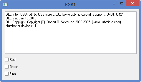
Image: RGB1.tBasic screen
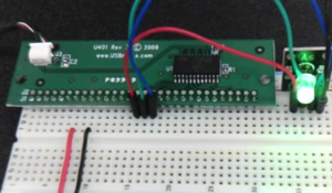
Image: Test result video
| Linked file: NVECapture.0002.mpg |
If you have more information about certain modules, please feel free to Contact us! and share what you know. If you also have test or application code to share, that link is the way to share that - we would appreciate your experiences and input a lot!
If you are interested in purchasing the unique devices that are shown on these pages, CircuitGizmos (link: CircuitGizmosOnline) sells many of these devices. Also Tindie has several of the CircuitGizmos devices for sale.
If you have questions about sensor modules like these, consider joining the Facebook group. Join the 37 Sensors FB Group! We'd love to see you there. If you are interested in the CircuitGizmos products, the FB page to join is CircuitGizmos on FB
Sometimes the 37 sensor projects are described as Instructables. This is the Instructable user to follow: Indestructable and YouTube channel and even follow on Instagram. Link back to us, please! We really like learning how our products are used.
All content, not otherwise posted with a copyright notice, is Copyright 2017+ to the owner of 37sensors.com.